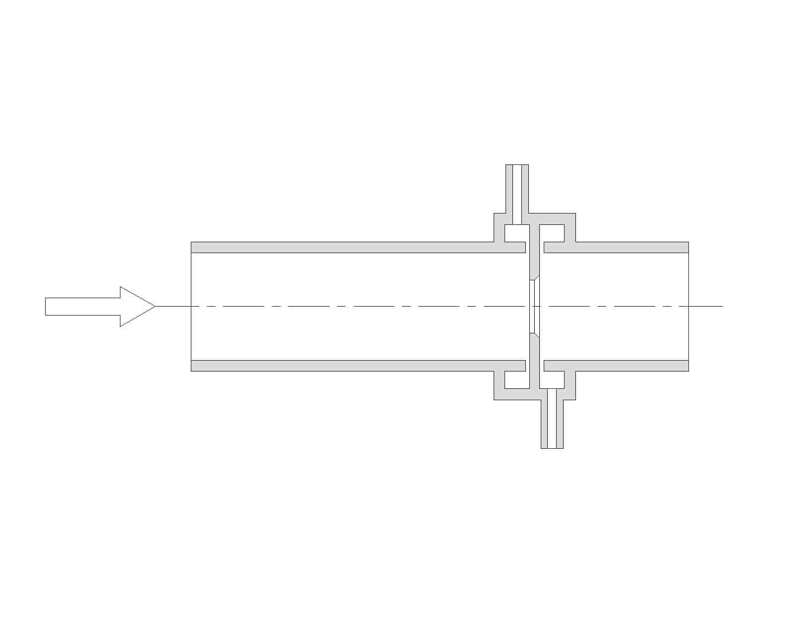
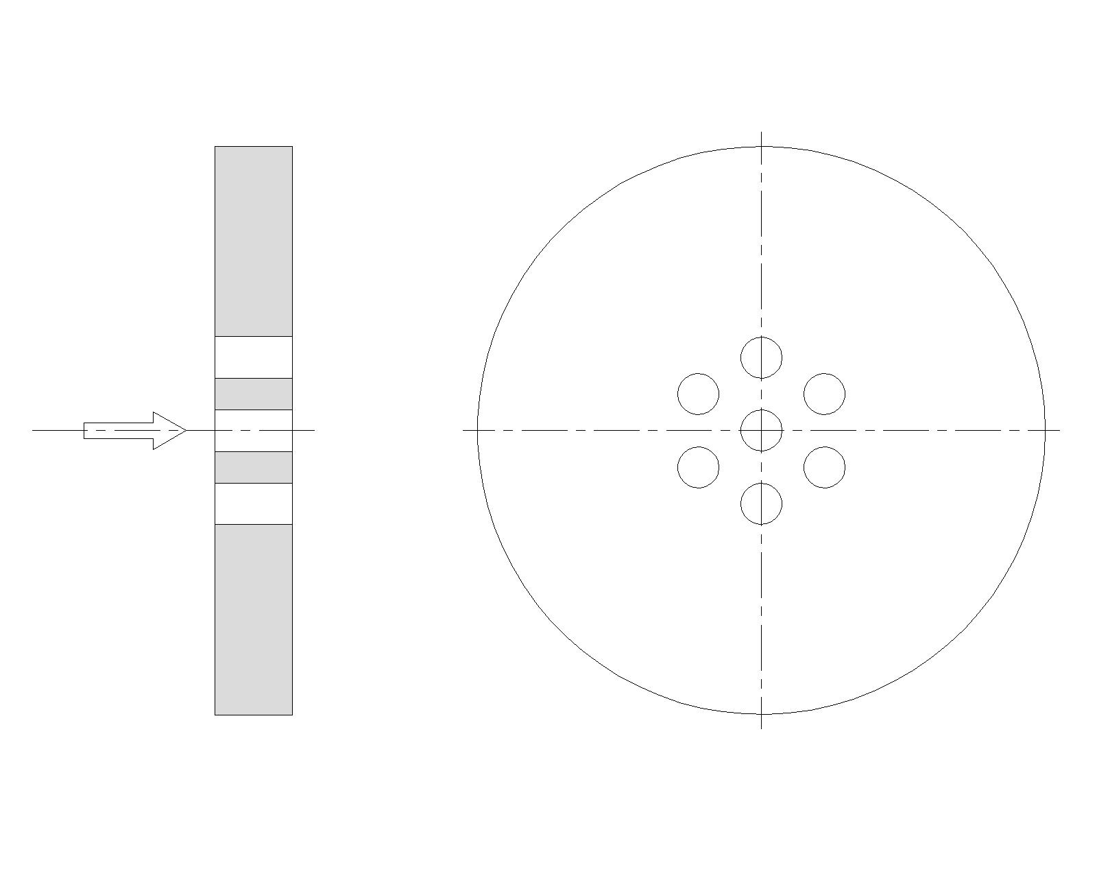
Flow meters working on the Δp principle, and especially orifice plates, are still widely used in the industry. Advantages of the orifice plate: their simple construction, tolerance to extreme process conditions and repeatable and reliable performance.
Cone meters work on the same principle as other primary elements. They are becoming very popular in the industry because they need very short straight pipe lenghts to make an accurate measurement. The profile of the primary element positively affects the velocity profile.
Nozzles are used when fluid velocity are too high to avoid erosion or cavitation of the primary element. It is the recommended primary element type for fluid flow measurement of saturated or superheated steam.
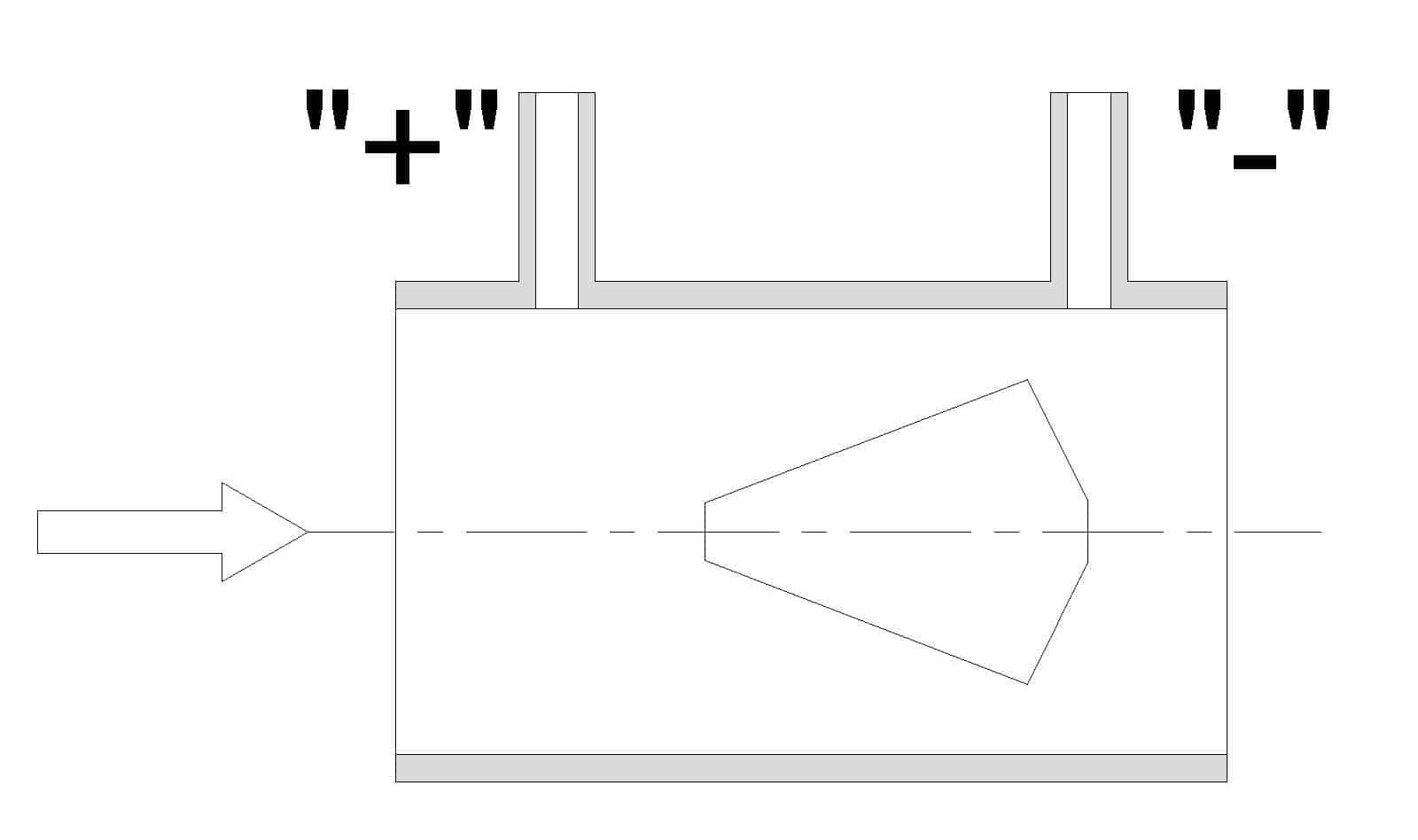
Although the design is similar to orifice plates, restriction orifice plates have a different function. They are used to create a pressure reduction in process lines or to restrict flow to a pre-defined value regardless of the downstream pressure. They are also used for:
Cone meters work on the Δp principle and are used for measurement of fluid flow (liquids, gas and steam). The profile of the cone positively affects the velocity profile so they need very short straight pipe lengths (3D and 1D, upstream and downstream, respectively).
Orifice plates are used for measurement of fluid flow (liquids, gas and steam). This measurement is based on the Δp principle. They are still widely used in the industry because of their simple construction and reliable performances.
Use: General use for all fluids
Bore diameter: d ≥ 12,5 mm
Pipe internal diameter: 50 ≤ D ≤ 1000 mm
Diameter ratio β=d/D: 0,1 ≤ β ≤ 0,75
Uncertainty of discharge coefficient: 0,5 ≤ δC/C ≤ 1,25 %
For pipes with internal diameter less than 50 mm metering runs are used.
Position of Δp tappings:
Flange tappings
Corner tappings
D and D/2 tappings
Meter run assembly is made out of stainless steel and it’s components are an orifice plate and the needed straight lengths before and after the orifice plate. This construction expands the field of use of the orifice plate.
Nozzles are used for measurement of fluid flow (liquid, gas, steam). It is based on the Δp principle. In comparison with orifice plates they produce less permanent pressure loss and they have a longer service life.
Use: General use for all fluids
Pipe internal diameter: 50 ≤ D ≤ 500 mm
Diameter ratio β=d/D: 0,3 ≤ β ≤ 0,8
Uncertainty of discharge coefficient: 0,8 ≤ δC/C ≤ 1,2 %
Tapping position: Upstream corner tapping, downstream corner tapping or distanced from the upstream face of the nozzle according to standard
Use: General use for all fluids
Nozzle throat diameter: d ≥ 50 mm
Pipe internal diameter: 65 ≤ D ≤ 500 mm
Diameter ratio β=d/D: 0,316 ≤ β ≤ 0,775
Uncertainty of discharge coefficient: 1,21 ≤ δC/C ≤ 1,74 %
Tapping positions: Upstream tapping D/2 from the convergent part, downstream tapping on the middle of the cylindrical throat of the venturi tube.
These types of plates are used when there is a requirement to reduce the process line pressure or to restrict the flow to a pre-defined value regardless of the downstream pressure.
Venturi tubes are used for measurement of fluid flow based on the Δp principle. They produce very low permanent pressure loss. By standard three types of venturi tubes are defined depending on the method how the convergent part has been made:
1-Venturi tube with an “as cast” convergent section
2-Venturi tube with a machined convergent section
3-Venturi tube with a rough-welded sheet-iron convergent section
Use: General use for all fluids
Diameter ratio β=d/D: 0,4 ≤ β ≤ 0,75
Pipe internal diameter: 50 ≤ D ≤ 250 mm
Uncertainty of discharge coefficient : δC/C = 1 %
Tapping positions: Upstream tapping D/2 from the convergent part, downstream tapping on the middle of the cylindrical throat of the venturi tube.
In order to connect transmitters with a process, you need some of the following accessories:
-shut off valves,
-fittings,
-tubes,
-adapters
-valve manifolds
Process connections accessories should be chosen taking care of:
-physical quantity that is measured (pressure, differential pressure, level, flow…)
-aggregate state of the fluid (liquid, gas or steam)
-fluid aggressiveness and
-mechanical and thermal properties of the fluid (pressure and temperature).
Recommendations for process connections Hook up diagrams
Technical characteristics of the equipment as well as data for selection and ordering are given in Equipment for process connections
In most cases when measuring fluid flow with a Δp device, the fluid density is considered to be constant and equal to the value used in the calculation of the primary element. If the density deviates from the design value, an error in flow measurement occurs. For applications that require high accuracy, it is necessary to determine the actual (working) density under operating conditions. Fluid density is very rarely measured directly, the most often used method for determining density is calculating it from operating conditions (pressure and temperature). The newly calculated density is used with corresponding equations to correct the measurement of fluid flow. IAPWS-IF97 is used to calculate steam and water properties.
PLC blocks are blocks that realize specific functions such as:
— Flow correction when Δp principle is used (flow of water, steam, natural gas…)
— Flow correction when Vortex, Electromagnetic, Ultrasound or Turbine flow meters are used
— Calculation of delivered heat energy
— Calculation of density, enthalpy…
One of the most used methods for fluid flow measurement in open channels is measuring the height of the fluid while it is flowing through a dam or weir of known geometry. Velocity and volume flow are calculated based on the contactless measurement of fluid height.
Analyzer panels/buildings are a combination of experience, practice, expertise and a desire to integrate all components in order to fully automate analytical measurements. We design, make, install, commission, and service the following systems.
Used for measuring and regulating combustion products in industrial plants. The measurement includes automated chemical analysis of the following chemical elements: CO, CO2, NOx, SO2 i O2. Measurement and regulation include other process parameters such as:
– Flue gas velocity (volumetric flow)
– Moisture content in flue gases
– Content of powdered materials
– Pressure and temperature
3B Inženjering offers an automated system for measuring and regulating the pH value of fluids in industrial plants, especially in the preparation of boiler water and wastewater.
Most often, the measurement and regulation of water conductivity is performed together with the measurement and regulation of the pH value of boiler water. These two parameters are key in pipe and boiler systems because they directly affect: sludge formation, formation of deposits that
Most often, the measurement and regulation of water conductivity is performed together with the measurement and regulation of the pH value of boiler water. These two parameters are key in pipe and boiler systems because they directly affect: sludge formation, formation of deposits that reduce head conduction, corrosion of metal surfaces. 3B Inženjering offers combined and separate systems for measuring conductivity and pH.
In industrial wastewater, the primary goal is the protection of the environment and its preservation. 3B Inženjering offers a solution for detecting wastewater oil.
Primary devices are restrictions that are installed in the pipeline. When fluid flows through the pipeline where the restriction is installed, there is a pressure drop, based on this pressure drop fluid flow can be determined. Primary devices are defined by the international standard ISO 5167 and ISO TR 15377. Based on these standards, 3B Inženjering calculates the dimensions, pressure drop, flow and measurement uncertainties.